The inertial locking box
|
Here is a novel box designed to unlock only when spun like a top. This project was inspired by a life-long fascination with puzzles, both mental and tactile. After being challenged by my coworker to build a spinning top, I decided to escalate and build a vessel that would only unlock if spun in the correct direction. Here's the result of weeks of diagrams, prototypes and general consternation.
Materials: Sterling silver, bronze, nickel, recycled ivory, mother of pearl Dimensions: 4" x 2" x 2" |
|
How does it work?
|
Security is two-fold on this vessel. A locking mechanism prevents vertical motion (i.e., the lid being lifted off), while a simple catch prevents rotational (unscrewing) motion. When both are in effect, the lid cannot be removed short of destroying the piece. Here's the lowdown:
The lock Check out the diagram on the left. Ignore the fancy pants double-layer wall and funny looking slots. Emerging from the top half is a threaded rod with a free-spinning nut mounted on it. The nut has little arms sticking out of it, giving it extra weight and, more importantly, rotational inertia. If I turn the upper half slowly in my hands as if I were going to spin it, we could see that the nut moves at the same rate as the rest of the piece. When I accelerate quickly, however, the nut is caught by its own inertia and is slow to move. For a few moments the nut has to travel up or down the screw until friction helps it catch up to speed. Huh. How does this act as a lock? Well, when we put the lid on the box we carefully feed the arms of the nut through a plate attached to the lower half (see left). The lid can only be removed when the arms are lined up with the slots on the plate. If I put the lid on and give the box just the right spin, the nut will travel up its thread and hit the bottom of that plate, locking the lid in to the lower half. So, what's the catch? Indeed, what's to stop the user from from turning the lid until the nut lines up with the slots and simply lifting it off? That's where the second catch comes in. In order to put the lid on, we must line up and navigate two little nubbins on the upper half through two tracks cut into the lower half. This type of catch is called a bayonet catch, for those who like to google. For those who don't, the diagram at left should suffice. As you can see, once the lid is in place it becomes impossible to rotate the two halves against each other. Now we spin the top. A few good spins will settle the traveling nut up against the locking plate, and bam. The top must now be spun in the opposite direction in order to open it. |
The process
|
As is common with this type of project, it began with a great deal of ponderFace, waking up in the middle of the night to scribble ideas, and impossible prototypes. Original ideas included overcomplicated spring-powered latches and multiple locking pins that shot out under centripetal force. Obviously, those didn't go anywhere.
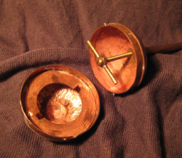
At left is my first successful prototype. It is made of copper and hardware, and is considerably less polished than the finished version. However, it was effective proof of concept. |
|
The prototype gave me valuable information on how to improve the design. For aesthetic reasons, I lengthened the body of the vessel to be more top-like and decided to make the final version in sterling silver.
I refined and streamlined the locking mechanism, thereby reducing the unnecessary friction in the system. This incarnation took far more time, care and attention to detail. At right is an exploded view of nearly all parts after completion, but before final assembly. Each component is hand-built using a variety of fabrication methods. The left- and right-most parts make up the body of the piece, and the other sections fit together inside to form the locking mechanisms. For assembly, all parts were silver soldered in their appropriate places. The inner screw and traveling nut are not shown here. |
 |
Room for improvement
|
I like to consider this an on-going project, as eventually I plan to further improve the design and explore other uses for my lock mechanism. My experimentation proved that while a more vertical design was both visually appealing and allowed greater room for the moving parts, it also made the top much more difficult to spin by hand. I suspect that there may be a happy medium that will satisfy both demands. In addition, It would be quite interesting to try using acme threads as opposed to a regular screw, as this might stabilize the motion of the nut.
Ultimately, I plan to try and design a 3D printable version of this box. Material constraints would likely require that the central screw and traveling nut be machined, but I suspect that the rest of the design could transfer over without too much fuss. On that note, I recommend you check out Thingiverse for some really neat examples of open-source 3D printable objects. |
If you've got ideas, comments or observations, I'd love to hear from you!
© 2013 Tess Myers all rights reserved